- Rumah
- Produk-produk
- LED adat
- LED panjang gelombang penuh
- LED IR
- Penerima IR
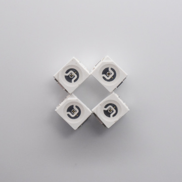
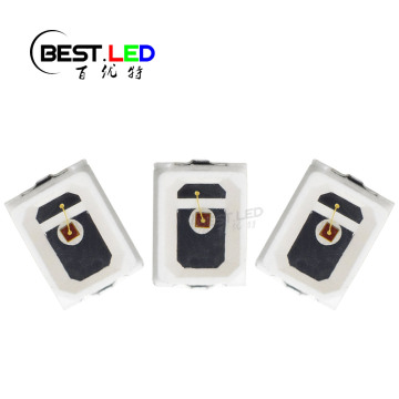
- LED SMD
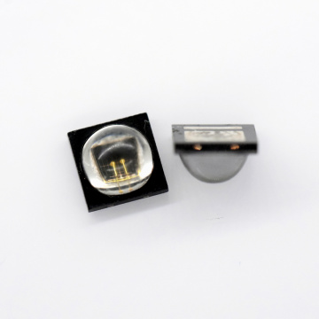
- LED berkubah
- Lampu LED.
- RGB LED.
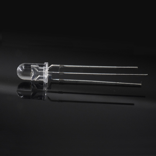
Lampu penunjuk bi-warna 5mm IR + LED kuning
Jenis bayaran: T/T,Paypal
Pengangkutan: Ocean,Land,Air
Atribut ProdukAtribut ProdukModel No.: 509FIRYGC
Jenama: LED terbaik
Jenis Bekalan: Pengilang asal
Bahan Rujukan: Lembaran data
Tempat Asal: China
Spesies: LED
Jenis Pakej: Melalui lubang
Application: Electronic Products
Luminous Intensity: High Directivity
Color: IR And Yellow Green
Formation: Gold Thread
Inner Packing: Anti-static Bag
Current: 20mA
Beam Width: 20 Degree
Polarity: Cathode on short pin
Wavelength: 880nm + 570nm (±10nm)
Lens Type: Clear lens
Pembungkusan & Penghantaran Unit Jualan : Piece/Pieces Jenis Pakej : Kotak karton Muat turun :  Penerangan produk
How does a 2 color LED work?
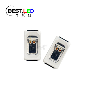
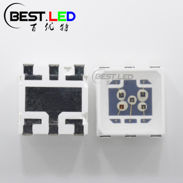
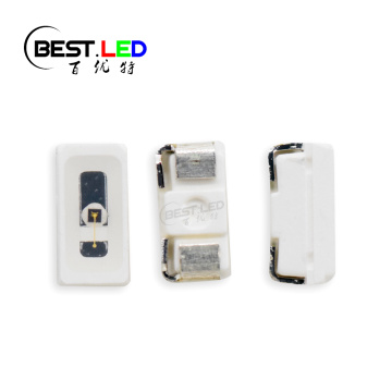
Bi-color LED can be package with SMD LED or through-hole LED Lamp type. In this 509FIRYGC, it's 5mm through-hole LED type with clear lens. Which can emits the full brightness from the LED chips. Then how does it work? Just following the datasheet and connect the correct polarity electric current, this LED will light up the color as you need. As the name, Bi-color LED lamps means that have two color inside one single LED package. We package yellow green color and IR LED (880nm LED) inside this LED Lamps case, which can make sure this 5mm bi-color LED can work good for status indicator and signage applications.
 Bi-Color Indicator Lamp IR + Yellow green Through-hole LED")
Size of 5mm bi-color LED:
 Bi-Color Indicator Lamp IR + Yellow green Through-hole LED")
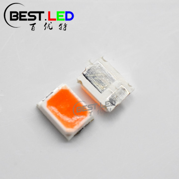
*This size are also available in IR LED, UV LED, Red LED, Yellow LED, Green LED, Amber LED and Blue LED;*
Electrical Optical Characteristics(Tc=25 ℃ )
Parameter Symbol Min Type Max Unit Test condition Forward Volatge
IR VF 1.3 1.4 1.6 V IF=20mA Green
2.2 2.5 IF=20mA Luminous Intensity IR IV
150
250 mcd IF=20mA
Green
10 mw/sr IF=20mA
Peak wavelength IR λP
875 880 890 nm IF=20mA
Green
570 575
Half width λ△
15
nm IF=20mA
Viewing half angle 2θ1/2
20
deg IF=20mA
Reverse current IR
5 uA VR=5V Production progress for through-hole LED:

Storage conditions
1. avoid continued exposure to the condensing moisture environment and keep the product away from rapid transitions in ambient temperature;
2. LEDs should be stored with temperature ≤30℃ and relative humidity<60%℃;
3. Product in the original sealed package is recommended to be assembled within 72 hours of opening;
4. Product in opened package for more than a week should be baked for 6-8 hours at 85-10℃;
LED MOUNTING METHOD
1, The lea d pitch of the LED must match the pitch of the mounting holes on the PCB during component placement ;
Lead-forming may be required to insure the lead pitch matches the hole pitch ;
Refer to the figure below for proper lead forming procedures ;
Do not route PCB trace in the contact area between the leadframe and the PCB to prevent short-circuits ;

2. When soldering wires to the LED, each wire joint should be separately insulated with heat-shrink tube to prevent short-circuit contact.
Do not bundle both wires in one heat shrink tube to avoid pinching the LED leads ;
Pinching stress on the led leads may damage the internal structures and cause failure ;

3. Use stand-offs(Fig 3)or spacers(Fig 4)to securely position the LED above the PCB ;
4. Maintain a minimum of 3mm cl earance between the base of the LED lens and the first lead bend (Fig. 5. Fig. 6)
5.During lead forming, use tools or jigs to hold the leads securely so that the bending force will not be transmitted to the LED lens and its internal structures ;
Do not perform lead forming once the component has been mounted onto the PCB ;

L ead Forming Procedures
1. Lead Forming Procedures ;
2 . Do not bend the leads more than twice (Fig. 7 );
3. During soldering, component covers and holders should leave clearance to avoid placing damaging stress on the LED during soldering(Fig 8) ;
4. The tip of the soldering iron should never touch the lens epoxy ;
5. Through-hole LED s are incompatible with reflow soldering ;
6. If the LED will undergo multiple soldering passes or face other processes where the part may be subjected to intense heat please check with Best LED for compatibility ;
 Membekalkan Keupayaan & Maklumat Tambaha...
Pembungkusan: Kotak karton
Produktiviti: 1000000000 pcs/week
Pengangkutan: Ocean,Land,Air
Tempat asal: China
Sokongan mengenai: 7000000000 pcs/week
Sijil: GB/T19001-2008/ISO9001:2008
Kod HS: 8541401000
Port: SHENZHEN
Jenis bayaran: T/T,Paypal
Incoterm: FOB,EXW,FCA
 Taipkan lubang melalui LED sebagai jalur kekili
Produk panas
SEND INQUIRY
- LED IR


 Bi-Color Indicator Lamp IR + Yellow green Through-hole LED")
 Bi-Color Indicator Lamp IR + Yellow green Through-hole LED")